Projectors based on 3LCD technology work by splitting the white light from the lamp into 3 beams colored red, green, and blue, passing each beam through one of three LCD panels, combining the 3 beams back into one through a prism, and finally focusing the combined beam onto a wall or screen. In this process, the positions of the three individual LCD panels must be carefully controlled to ensure proper convergence. If a panel becomes misaligned, the corresponding color will be offset from the other colors in the image a condition known as misconvergence.
Small misalignments by a pixel or less are usually tolerable when displaying videos and motion pictures. When text is displayed however, even a misalignment of only one pixel can lead to blurry text that is hard to read. The problem is worst for small fonts whose characters may only be one to two pixels wide.
To fix the problem the convergence must be adjusted by realigning the LCD panels. Advanced projectors offer this option through the projector’s software interface but cheaper models lack any control over convergence. The Sharp NoteVision XG-P10XU is one such projector. The convergence is set at the factory and the unit sealed so that the user is forced to accept any misalignment in the purchased unit or that may develop over time. This post shows how to adjust the convergence of the Sharp NoteVision XG-P10XU 3 LCD projector by opening the case and accessing the optical bench inside. The process should be analogous for any 3LCD based projector.
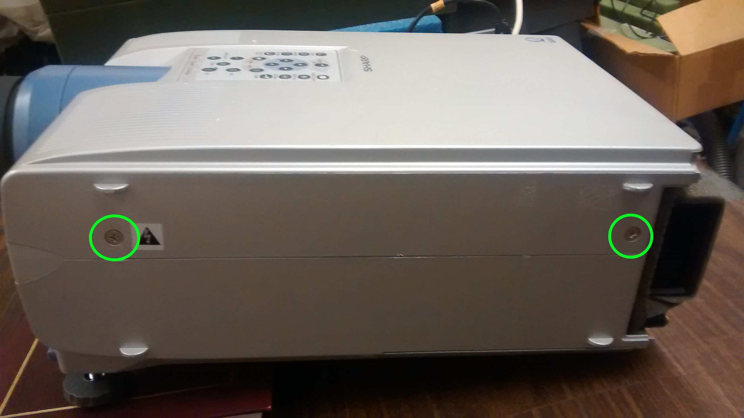
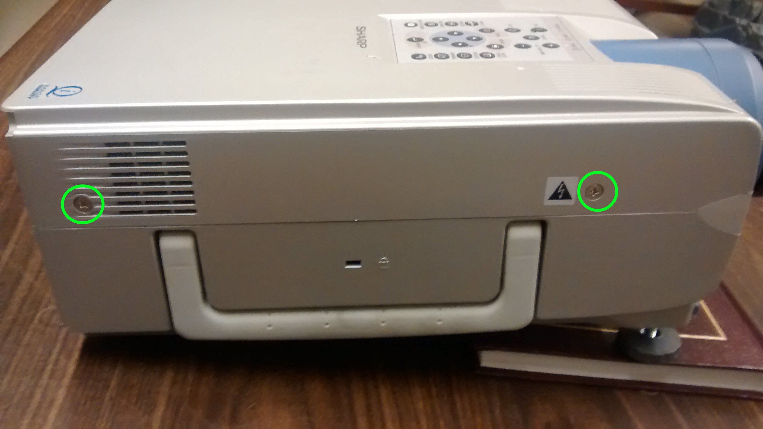
The first step is to remove the external screws and top cover. There are 15 screws total to remove and all can be removed with a philips screw driver. The screw positions are:
- 2 screws on the left side of the unit
- 2 screws on the right side of the unit
- 1 screw on the front below the lens (secures the lens collar)
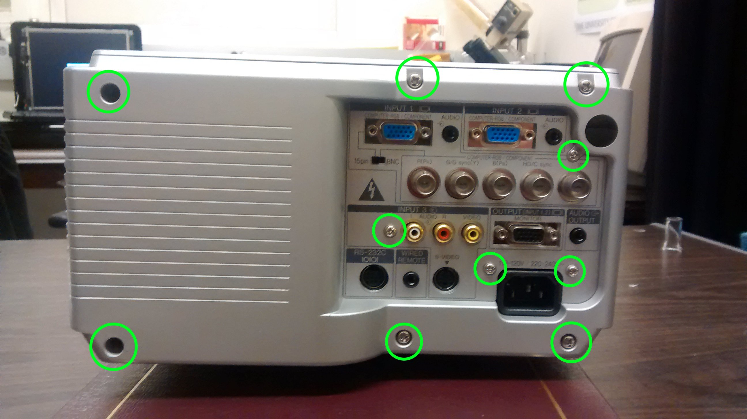
- 6 large screws around the perimeter of the back side
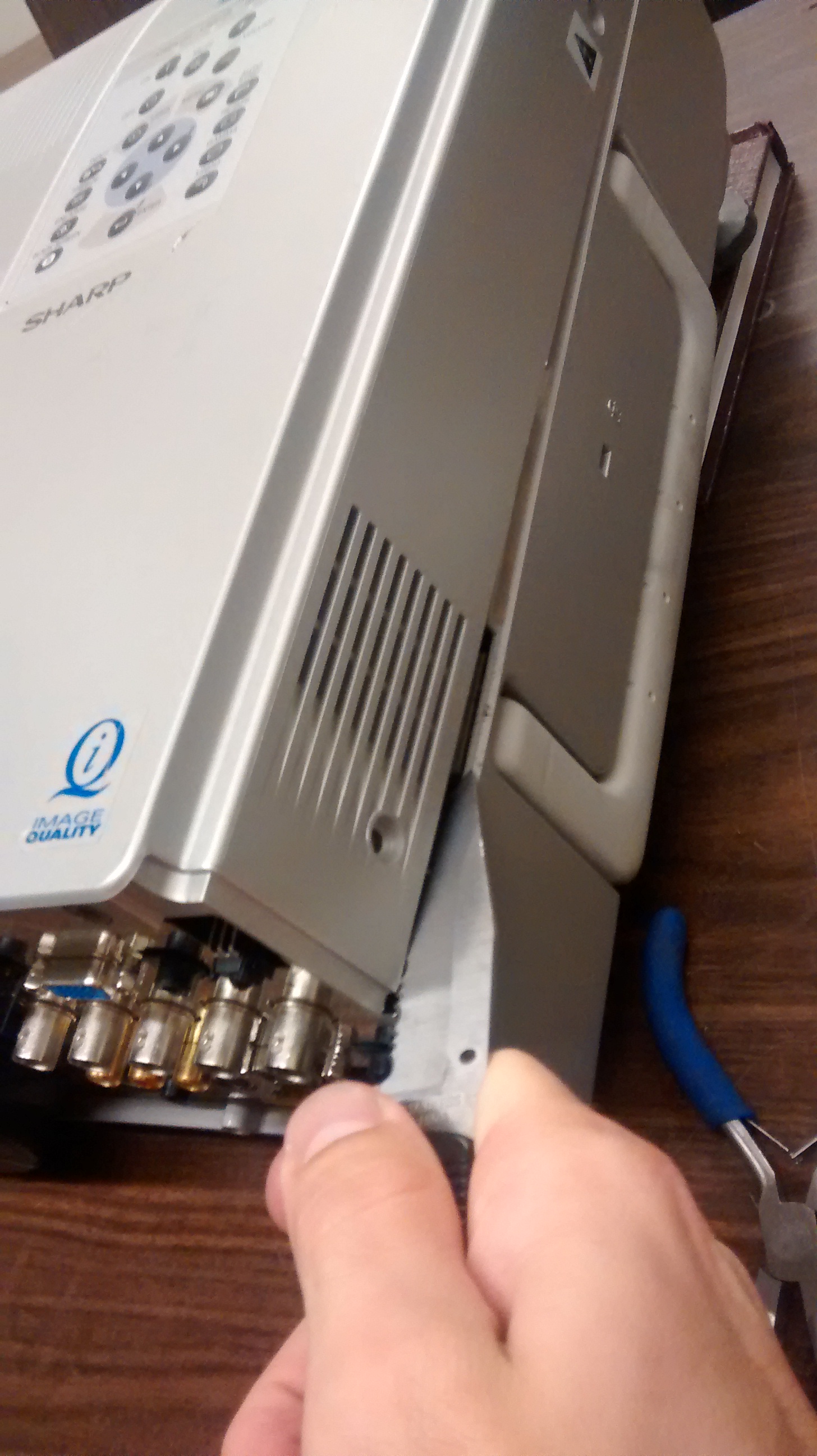
- 4 small screws on the back among all of the ports and connectors
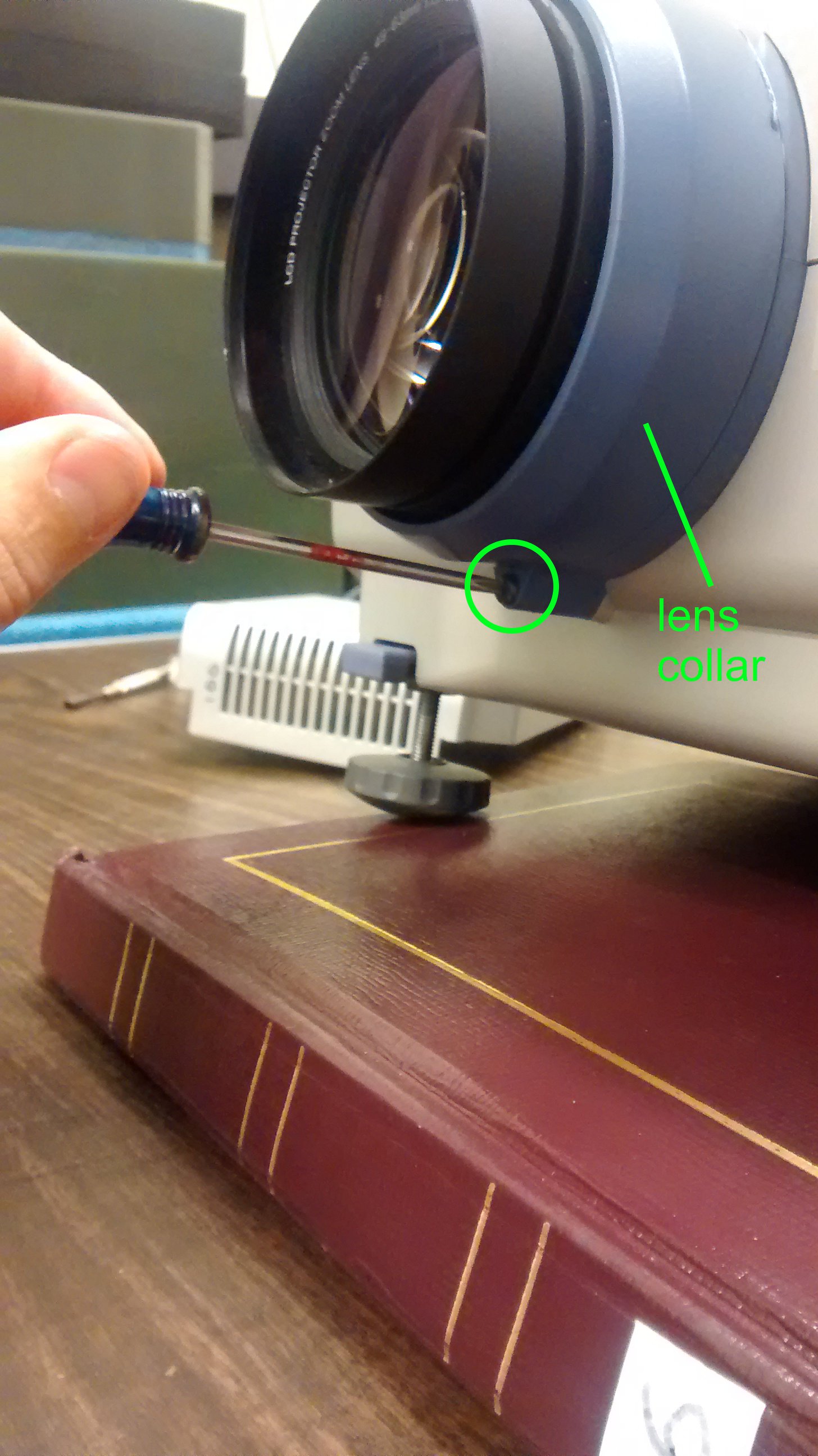
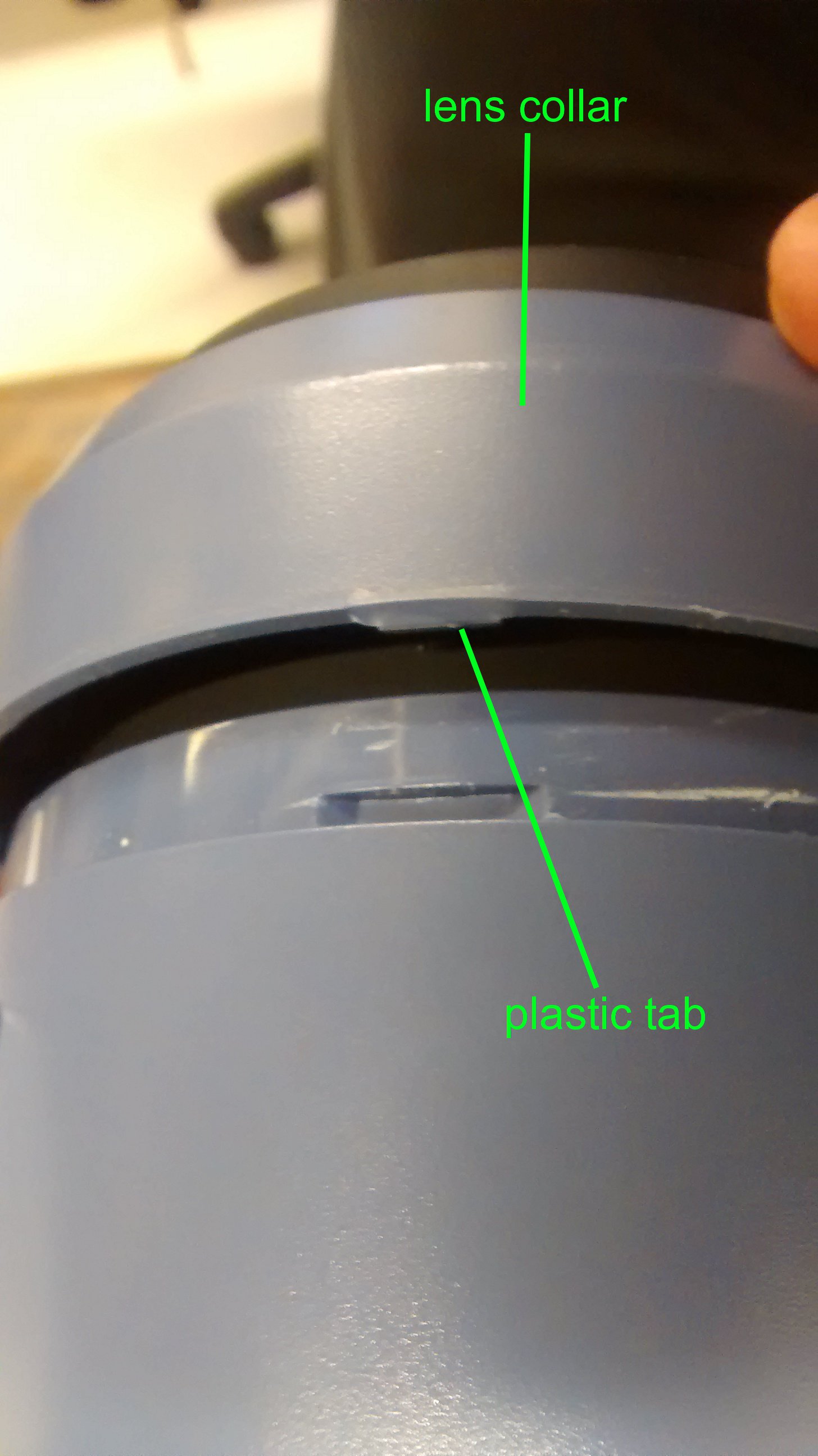
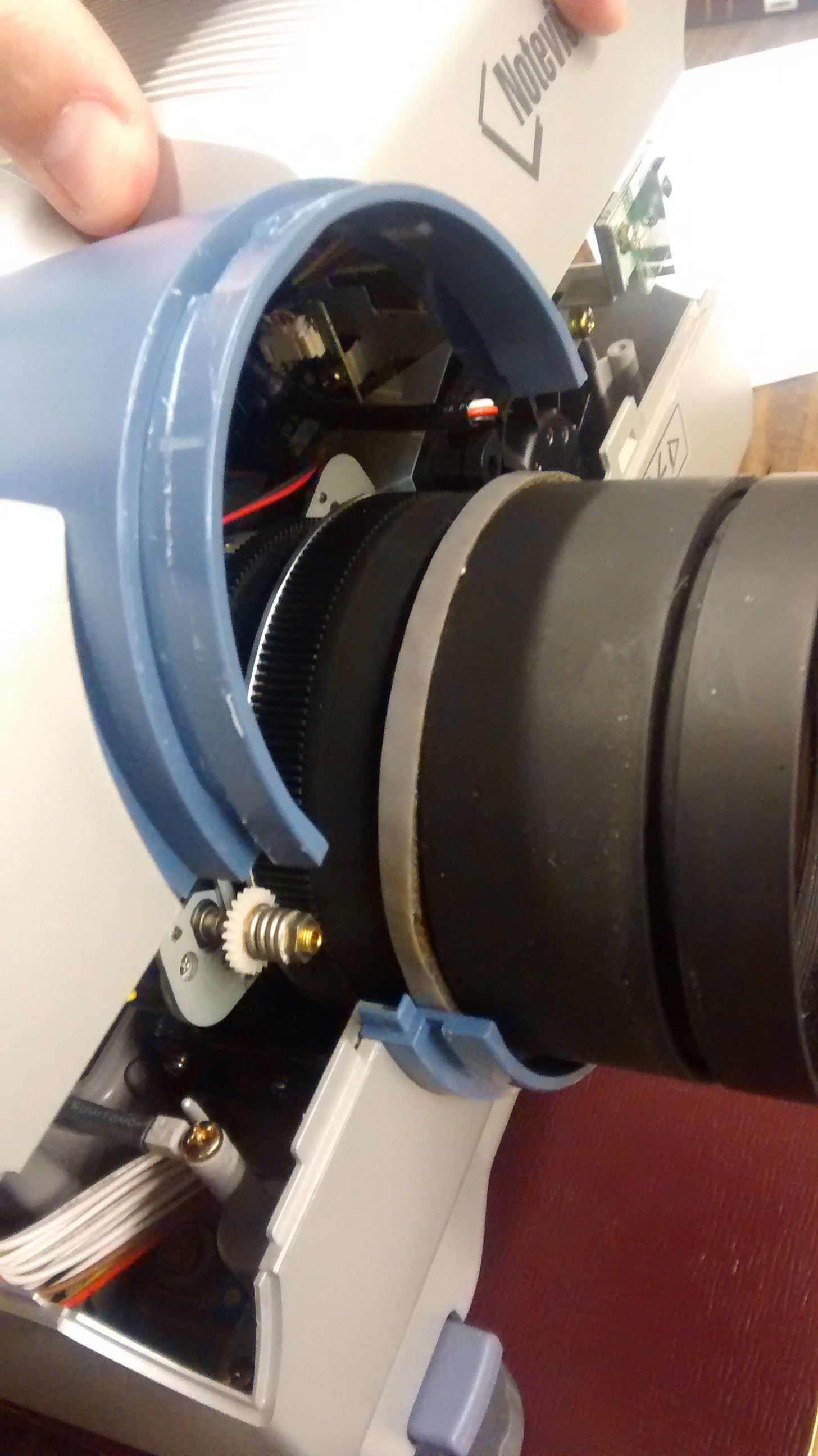
The back cover should come off easily now. The blue lens collar on the front should be pulled off. It has small plastic tabs holding it in place. A knife can be used to pry the collar off.

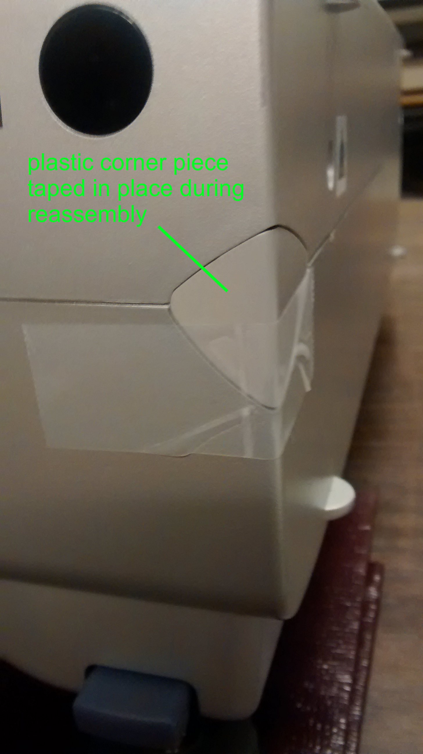
Only after the back panel and lens collar are removed can the top cover by taken off. Once again, small plastic tabs make this slightly challenging but a knife inserted in the crevice between the top and bottom covers and bent up and down works well to separate the two. At the front two corners are small plastic pieces that will fall away. Be careful not to lose them down inside the projector. The top cover can only be pulled a few inches up from the unit because there are wires running to the speakers mounted on the cover as well as a ribbon cable running to the control panel. It is only necessary to unplug the speaker wires from the projector. Set the top cover off to the side a bit with the ribbon cable still attached. Later you will operate the projector in this state and it will be necessary to use the control panel.
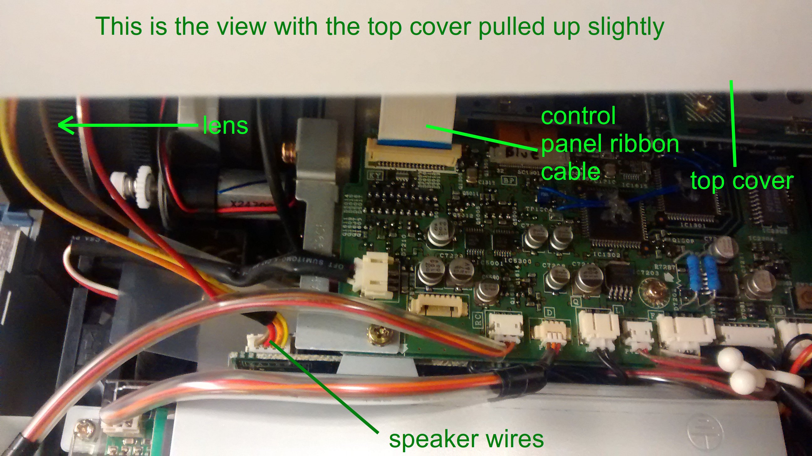
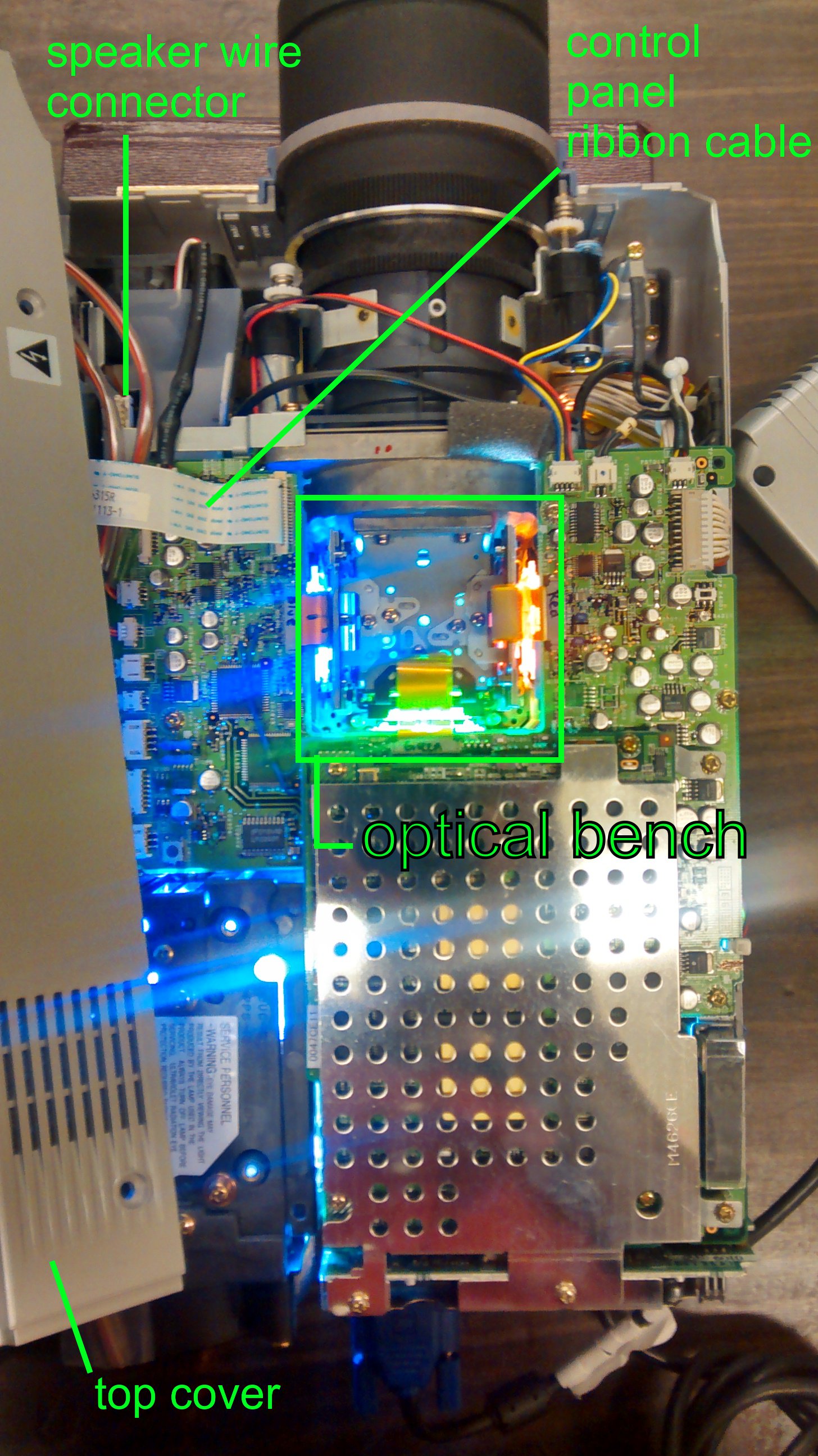
That completes disassembly. You should now have access to the optical bench in the center of projector just behind the lens. You will see three ribbon cables that lead to each of the three LCD panels. The panels are mounted vertically and are hard to see clearly buried beneath all of the circuit boards. The square area between them holds the prism that recombines the beams and reflects them into the lens.
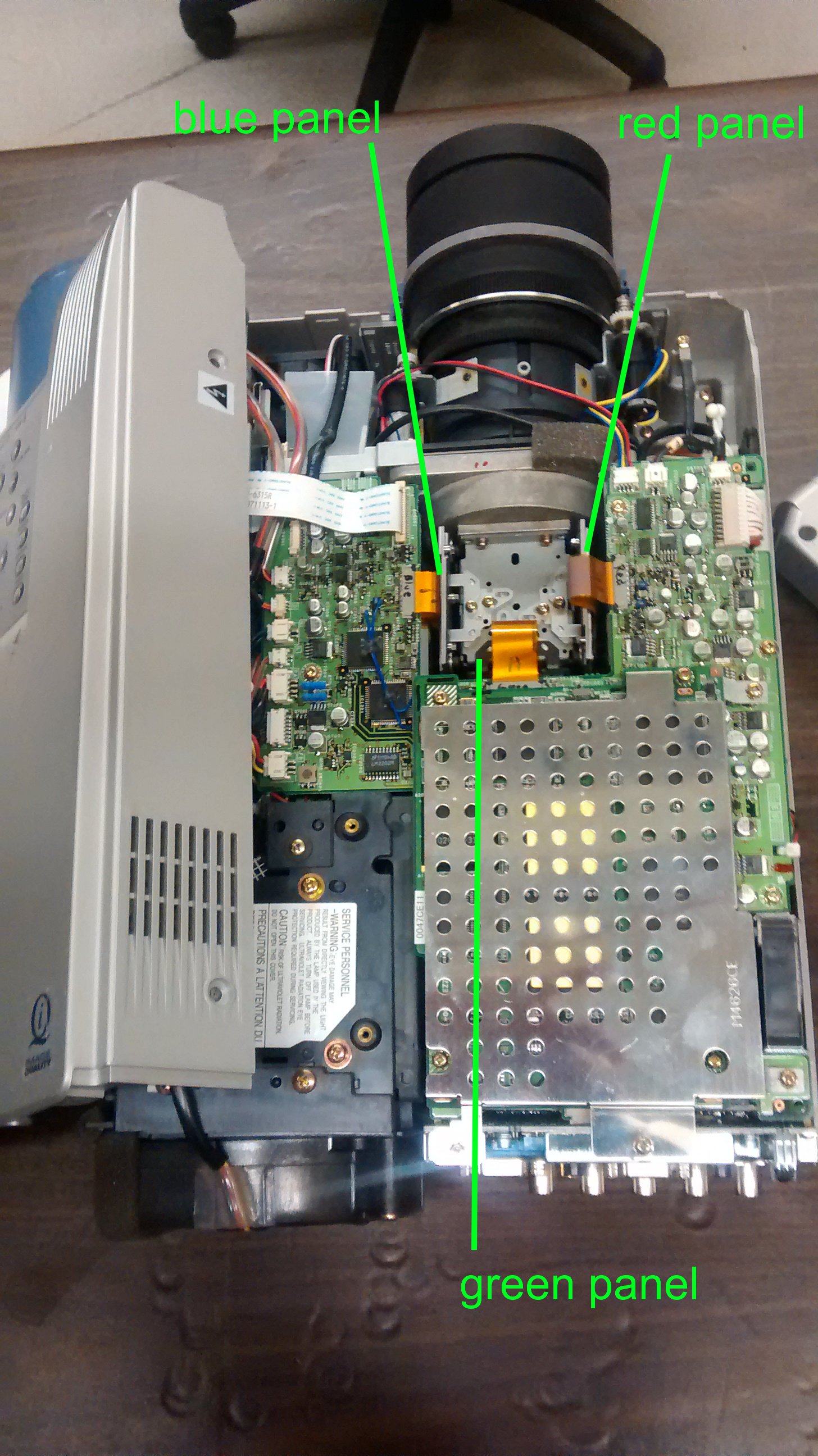
When standing at the rear of the projector so that it is pointed away from you, the left most panel is for the blue component, the center panel is green, and the right panel is red. If you look closely on the circuit boards near the ribbon cables that run to the panels will be the codes BP, GP, and RP for blue panel, green panel, and red panel, respectively. If you are attempting to adjust the panels on a different model and aren’t sure which is which, do not fret. Once the projector is turned on it will be obvious which panel is which.
WARNING! There are serious risks to operating the projector with the cover off. You are exposing yourself to dangerous voltages. DO NOT TOUCH ANY OF THE EXPOSED CIRCUITS OR WIRES. For maximum safety, wear latex or nitrile gloves. Be extremely careful not to short any of the circuits on the exposed PCB’s. Do not drop screws or metal tools onto the boards or into the unit. Try to have only one tool in your hand at a time and grasp it securely. Watch out for the cooling fans. Don’t stick anything in them, especially not your fingers. If you proceed to any of the following steps you do so at your own risk. I am not liable if you hurt yourself, the projector, or your surroundings.
To adjust the panels it will be necessary to operate the projector with the cover off. Plug in a video source and the unit’s power cable. Turn the projector on and focus it onto a white wall or screen in a dimly lit or dark room. It’s best. to connect a computer and have open a graphics-editing application. To gauge the alignment, I recommend long horizontal and vertical bars drawn in white on a black background. Make sure the bars are not anti-aliased. The pencil tools in MS Paint and GIMP work well for this. You may find that inverting the colors helps as well, especially to gauge the alignment of the blue panel. Test patterns can also be found online and displayed.
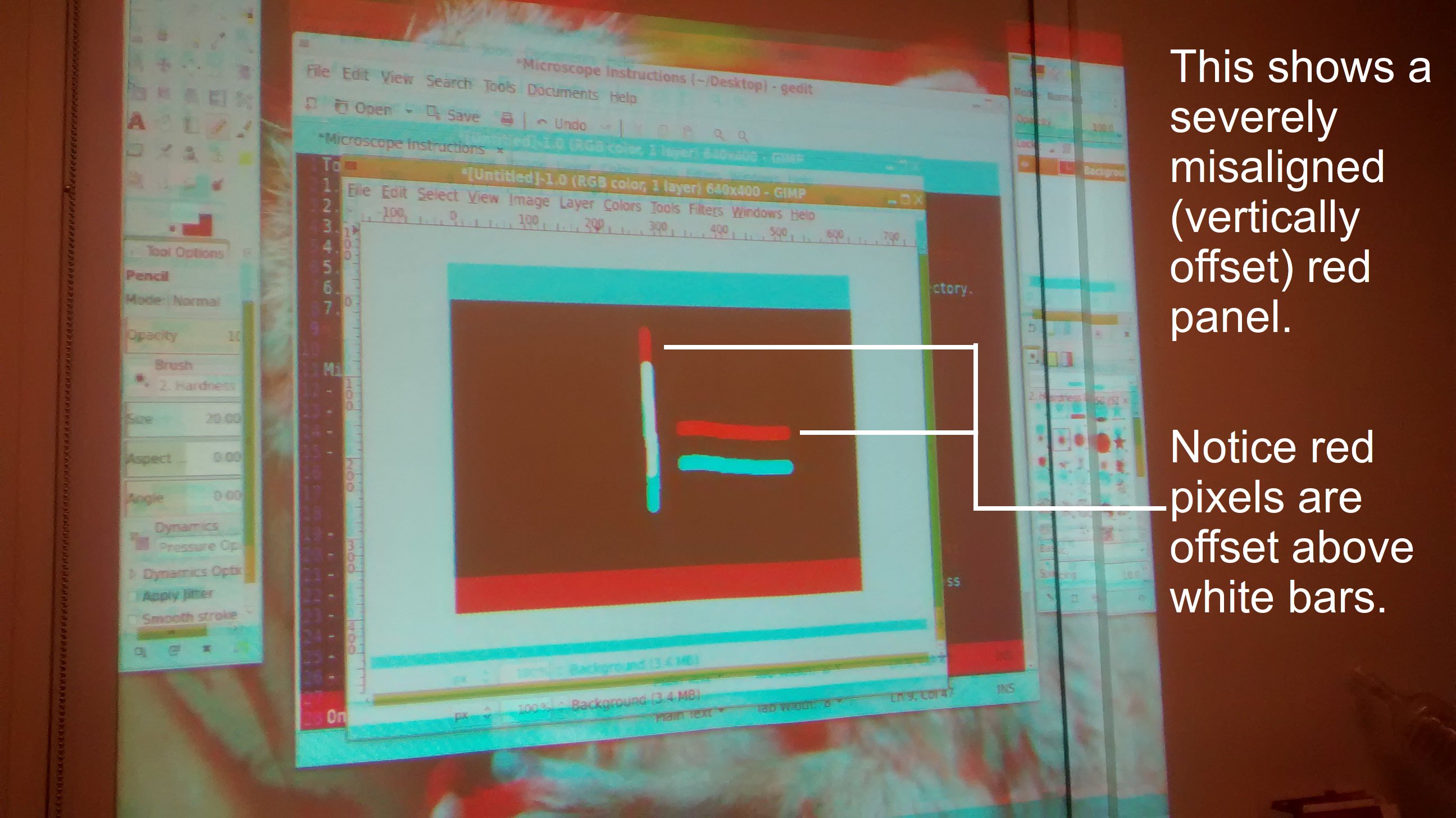
Inspect the displayed image and try to determine which colors are misaligned. The green panel in this projector is fixed as in most 3LCD projectors. You will be adjusting the red and blue. In the case of red and for the white line drawn on black, along the outer edge of the white line look for red pixels. If the panel is too far to the right, the outer right edge will be lined with red pixels and consequently the inner left edge will be lined with bluish-green pixels. For blue you’re looking for extra light blue pixels on the outer edge and yellow pixels on the inner edge.
Choose a panel to adjust first. You must loosen the retaining (locking) screws of the panel so that it can be adjusted. In this model, these are the two small black hex screws that run horizontally. Do not remove them, just loosen them a bit. You will need a hex wrench here. Now the panel can be adjusted by turning the hex bolts near the top of the panel. There is a bolt for vertical and a bolt for horizontal position. Some units will have screws instead of hex bolts and some may have a tilt adjustment as well. A pair of pliers may be needed to turn the adjustment bolts.
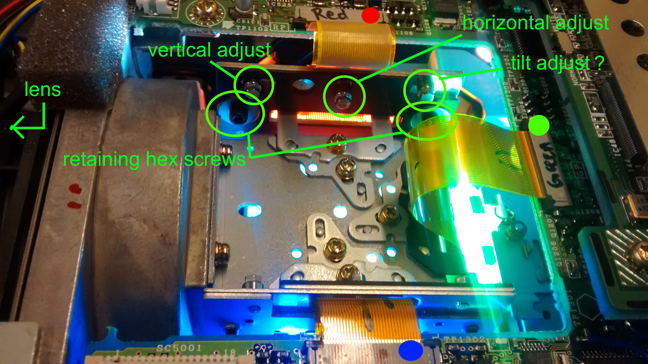
Adjustments should be in small increments. If you make a large adjustment, the beams will become severely misaligned. This might be a good way to determine which adjustment bolt moves what direction. Keep adjusting the bolts until you can no longer see extra colored pixels offset from the white bars (or black if on a white background). Go slowly and be patient. Sometimes, the best you can do is about +/- 1/2 pixel. When you feel satisfied with the adjustment, re-tighten the retaining screws (hex screws). Make sure they’re tight enough that bumps and heat won’t displace the panels again.
Repeat for the other panel and you’re finished. Turn off and unplug the projector. Then reverse the disassembly steps to replace the top cover, back cover, and lens collar. Don’t forget to plug the speakers back in. I recommend to tape the front plastic corner pieces in place until the unit is fully reassembled. Here’s hoping all went well.