5890 Remote Panel – Control an HP 5890 over RS-232

My latest project is setting up an HP 5890 Series II Plus gas chromatograph. One challenge with operating older lab equipment is always accessing and storing the data they produce. Commercial options sometimes exist, but are often cost prohibitive for individuals. Introduced in 1984, the HP 5890 set the standard for gas chromatographs. According to Agilent, the instrument-centric spin-off of HP, the 5890 is the best-selling GC in history (https://www.chem.agilent.com/cag/aboutapg/abouthistory.html). Many of them are still in use in laboratories around the world, including at my current place of employ. And yet, there has been little software support from the open-source community. In setting-up my 5890, I intend to write software along the way and offer it to the world freely, under an unrestrictive open-source license, the GPL. 5890 Remote Panel is the first piece of software I’ve produced. Hopefully in time there will be more.

So what is 5890 Remote Panel? It is the product of my initial experimentation learning to communicate with the 5890 of an RS-232 interface. One of the simplest and most powerful commands the 5890 understands is the RK (Remote Keystrokes) command. This simple command simulates key presses from any of the keys on the 5890 keyboard. 5890 Remote Panel is written entirely around this one command. It allows remote operation of the 5890 GC through a virtual keyboard, just as though the user were standing at the physical instrument. This could be extremely useful for people who have a 5890 with a non-functioning keyboard, for example. Or perhaps one might need to start/stop a run, monitor run time, or change temperature settings from another room or, with a remote desktop connection, from anywhere in the world. This initial version does not record or process any chromatograms from the GC. If you need that kind of capability, take a look at UniChrom (http://www.unichrom.com) which provides support for 5890’s.

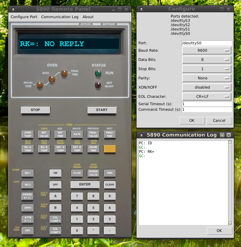
5890 Remote Panel is written entirely in Python3 and depends on the serial, tkinter, ttk, time, and re libraries, all of which are standard Python libraries. It should operate on any platform that supports Python3 (OSX, Windows, Linux, etc) but has been tested only on Debian GNU/Linux (kernel 4.2.6-1). It is released under GPLv3 and can be downloaded as a zip file using this link:

Download 5890 Remote Panel

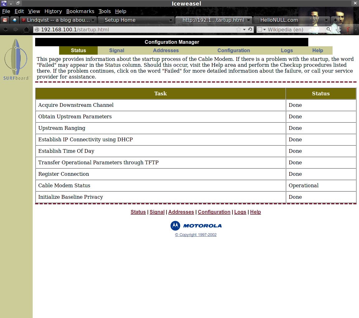
Here is a screenshot and below one can find the technical details of operation.

5890-remote-panel-screenshot

Operation:

The HP 5890 can have one of two different serial interface cards that I know of, the 19242-60030 and the 19257-60010. Both cards understand similar commands but the syntax used is different. 5890 Remote Panel is written to communicate with the 19257 card only. Communication works as a conversation initiated by the PC. A command is sent to which the GC will issue a reply. The link below lists the available commands with short descriptions.

HP 5890 19257A Serial Interface Command List

Many commands need parameters and this simple document gives no details. The best source I’ve found so far is the HP 5890 Serial Interface Manual, part 19242-90120, for the 19242 series card (special thanks to Gerard Spain at the Mace Head Atmospheric Research Station of the National University of Ireland, Galway). Other DIY-er’s may email me if they are interested in the contents of that manual.

The baud rate for the 19257 card is set by a small, 8-position switch block labeled S1. For RS-232 communication (rather than GPIB), positions 7 (SRQ_EN) and 8 (GPIB) must be set to off (0, toward the outer edge of the board). Positions 1, 2, and 3 then determine the baud rate. All switches on gives the lowest possible rate of 150 bps. All switches off gives the highest rate of 19200 bps. The other available rates are 300, 600, 1200, 2400, 4800, and 9600. The details of the switch configuration can be found in the Installation Guide for the Agilent GPIB/RS-232 Interface Kit, Accessory 19257A (manual part number is 19257-90107). The baud rate can be verified by holding down the CLEAR button on the GC keyboard while the GC turns runs through its self tests after turning it on. This will take you to a communications test menu and the display will read “User Tests Sel 0..7”. Test 4 will display the current RS-232 baud rate.

When 5890 Remote Panel loads, it first tries to open serial port “/dev/ttyS0” using the pySerial library. That port is the default because that was the one I needed on my own PC. There is a configuration dialog that allows the user to change the port, though any setting changes will be forgotten when the program is closed. Of course, since the program is distributed as Python source code, any defaults can be freely modified. The HP 5890 Series II Plus uses the settings below by default.

  • data bits = 8
  • stop bits = 1
  • parity = none
  • hardware handshaking = none
  • end-of-line character = CR+LF

Once the port is successfully opened, the program sends out the test command “ID” and listens for a reply which should be “IDEN HP19257A Rev C” or similar. As long as some reply is returned, the program will assume it is correctly connected. It next issues an OT (output) command “OTRemote Panel OK” which, if successful, will change the LED display on the 5890 to read “Remote Panel OK”. The 5890 should respond with “OTEN” which stands for “output end”.

At this point the programs waits for user interaction. Each time the user clicks one of the buttons on the virtual keyboard, the program issues a remote keypress (RK) command to the GC with the keycode of the button clicked. For example, to simulate the pressing of the “OVEN” key, the command “RKG” is sent. The GC will response, e.g. “RKENOVEN TEMP 40 40” contains the contents of the GC’s LED display after the “RKEN” prefix. The virtual display is updated to match the GC display based on this reply.

DSC alarm system installer codes and user access codes

My new habitat came protected by a DSC alarm system. The system consists of a keypad, model RFK5501 in my case, and a control panel, PC1616 for me. The model number of the keypad is hidden in very tiny text on the top edge of the keypad. The control panel is the hub of the alarm system and is located within a metal box within an interior wall. I had to open the metal enclosure to find the model number of the control panel.

To change most settings one needs a user access code. For the PC1616, there are 48 user access codes numbered 01 through 48. Other models have more codes. Access code 40 is the master code. This code can be used to change all other codes. To change a user access code, one would enter *5[master code][code #][new code]. So, for example, if the master code is 1234 and one wants to add a second code (01) as 5678, one would enter *5 1234 01 5678. To change the master code to 5678, the sequence is *5 1234 40 5678. In the sequence, after each accepted entry, the keypad will emit three beeps. When an entry is rejected, it will sound one long beep. When finished, pressing # until the ready light comes back on and the screen blanks will return the keypad to normal operation.

Changing the master code is one important level of security, but there is an even more privileged code with which a person could compromise the DSC security system. This code is the installer code. With the installer code, it is possible to change the master code and all other settings. New systems come with a default installer code programmed, 5555 in the case of the PC1616. If the installer hasn’t changed the installer code, it’s a good idea to change it since it potentially allows anyone to have control over your security system. DIY’ers should change the code regardless to prevent unwanted access from even the installer.

The installer code is changed by entering the installer programming via the *8 command. The complete sequence is *8[current installer code]006[new installer code]. For example, the following sequence sets the default installer code (5555) to 1234: *8 5555 006 1234. Then the # key is pressed until the keypad returns to normal operation. In the case of entering the installer code, an accepted code is signaled by six short beeps instead of three.

If the new installer code is forgotten, the code can be reset to the default code following a hardware reset procedure at the control panel. For maximum security, there is an installer lockout feature that will prevent the hardware reset from resetting the installer code. If the installer code is unknown and the installer lockout is enabled, the only solution to regain complete control of the system is to replace the control panel with a new panel in factory default condition.

Finding the area under a curve with a spreadsheet program (Excel, Libreoffice Calc) or QtiPlot

For performing elemental analysis by x-ray photoelectron spectroscopy, I needed to integrate and find the area under the peaks in some spectra. One approach is to fit each peak with a Gaussian function and use the area of the Gaussian. For some convoluted peaks, I wanted something simpler. I wanted to get the total area under each peak without fitting it in any way.

I use QtiPlot almost exclusively for plotting and fitting (fityk is my other go-to program) and one of the menu options for plots is Analysis->Integrate. That option brings up a tiny dialog where you can select the curve and range over which to integrate.

Screenshot - 10282014 - 09:13:32 PM

In the results log, an area is printed for the integrated curve. I wasn’t sure what QtiPlot was doing so I did an experiment with a simple set of data. I now know conclusively the algorithm used by QtiPlot and am able to replicate it in a spreadsheet program. I use LibreOffice Calc, but the instructions here should work in Excel as well.

Given a set of n points, P1 through Pn, a curve is generated by connecting each point with straight lines.qtiplot-integration-plot1

The area under the curve between two points, (x1, y1) and (x2, y2), is a trapezoid with area A = 1/2 |x1 – x2| (y1 + y2).qtiplot-integration-plot2

To find the area under the curve defined by a set of points, QtiPlot iterates through the points from P0 to Pn-1. For each point Pi, it calculates the area using Pi as (x1, y1) and Pi+1 as (x2, y2) and sums all of the trapezoid areas.

The above process is easy to replicate in LibreOffice Calc (or Excel) with the x,y data that define the curve. Assuming the x coordinates are in column A starting at row 1 and the y coordinates are in column B starting row 1, the areas of the individual trapezoids can be generated in column C. The formula in the first row is: “=0.5*abs(A1-A2)*(B1+B2)”. That formula is then copied down column C in all of the rows but the last. Finally, the areas are summed to give the total area under the curve.

Screenshot - 10282014 - 09:48:15 PM

Will that motorcycle pay for itself really?

In deciding whether or not purchasing a motorcycle is a prudent decision, cost plays a significant factor. Motorcycles often get much higher gas mileage (fuel efficiency) than cars. A common belief is that because of this fact, a motorcycle might pay for itself. I wanted to believe this is true, but after running the numbers, this belief is a myth and is only true in extreme circumstances. I’m recording the relevant equations here so that next time I get the impulse to by a motorcycle, I won’t use cost savings as a justification.

In my situation, my everyday car, the Edscort, gets about 34 mpg highway, 30 mpg city. I don’t think I’ve ever seen less than 30 mpg so I’m going to use that figure as the Edscort’s fuel efficiency. The motorcycles in which I’ve been interested have been around $1500 in cost and achieve about 60 mpg. For simplicity’s sake, I will ignore the cost of insurance, maintenance, and accessories.

The cost, c, to drive a vehicle m miles is given by:

eqn1

where f is the fuel efficiency of the vehicle in mpg and r is the cost of gasoline in $/gal. The cost savings Δc is the difference in the cost of driving those miles with the motorcycle (bike) vs. the Edscort (car). A negative value for Δc corresponds to money saved.

eqn2

In order for the motorcycle to pay for itself, the cost savings must be at least as much as the purchase price of said motorcycle, P. That is, -Δc = P, where the negative sign makes a negative cost differential equal to a positive purchase price. The number of miles that must be driven before the bike pays for itself is therefore:

eqn3

In my case, where the Edscort gets 30 mpg, the motorcycle gets 60 mpg, gas is $3/gal (as of this writing, it’s $2.99/gal down the road) and the motorcycle purchase price is $1500, I would need to drive the motorcycle 30,000 miles to break even. And note, these trips on the motorcycle must be in place of rides in the Edscort, not in addition to my usual driving.

To point out how impractical this is, consider that I’m currently averaging about 10,000 miles per year driven. If I can substitute the motorcycle for 20% of those miles, I’ll put 2,000 miles on the bike per year and it will pay for itself in only 15 years. I could cut that to 6 years if I substitute the bike for 1/2 of my normal driving. Ideally, I’d want the bike to pay for itself in 2 or 3 years, but that’s obviously not going to happen.

New bikes are considerably more expensive and I’ve not considered other ownership costs in which case things get even worse. Of course, reducing the wear and tear on the Edscort might stave off a significant repair bill, but there’s no guarantee that’s the case. Nor is there a guarantee that the bike won’t need a major repair itself.

The bottom line is that cost savings cannot be used to justify the purchase of a motorcycle. The decision to buy one is not a practical decision. Face it.

How to align the red-green-blue (RGB) LCD panels (adjust convergence) of a Sharp XG-P10XU Projector

Projectors based on 3LCD technology work by splitting the white light from the lamp into 3 beams colored red, green, and blue, passing each beam through one of three LCD panels, combining the 3 beams back into one through a prism, and finally focusing the combined beam onto a wall or screen. In this process, the positions of the three individual LCD panels must be carefully controlled to ensure proper convergence. If a panel becomes misaligned, the corresponding color will be offset from the other colors in the image a condition known as misconvergence.

Small misalignments by a pixel or less are usually tolerable when displaying videos and motion pictures. When text is displayed however, even a misalignment of only one pixel can lead to blurry text that is hard to read. The problem is worst for small fonts whose characters may only be one to two pixels wide.

To fix the problem the convergence must be adjusted by realigning the LCD panels. Advanced projectors offer this option through the projector’s software interface but cheaper models lack any control over convergence. The Sharp NoteVision XG-P10XU is one such projector. The convergence is set at the factory and the unit sealed so that the user is forced to accept any misalignment in the purchased unit or that may develop over time. This post shows how to adjust the convergence of the Sharp NoteVision XG-P10XU 3 LCD projector by opening the case and accessing the optical bench inside. The process should be analogous for any 3LCD based projector.

The first step is to remove the external screws and top cover.  There are 15 screws total to remove and all can be removed with a philips screw driver. The screw positions are:

  • 2 screws on the left side of the unit
  • 2 screws on the right side of the unit
  • 1 screw on the front below the lens (secures the lens collar)
  • 6 large screws around the perimeter of the back side
  • 4 small screws on the back among all of the ports and connectors

projector left view projector lens collar screw projector rear view projector right view


The back cover should come off easily now. The blue lens collar on the front should be pulled off. It has small plastic tabs holding it in place. A knife can be used to pry the collar off.

projector rear cover off projector removing lens collar

Only after the back panel and lens collar are removed can the top cover by taken off. Once again, small plastic tabs make this slightly challenging but a knife inserted in the crevice between the top and bottom covers and bent up and down works well to separate the two. At the front two corners are small plastic pieces that will fall away. Be careful not to lose them down inside the projector. The top cover can only be pulled a few inches up from the unit because there are wires running to the speakers mounted on the cover as well as a ribbon cable running to the control panel. It is only necessary to unplug the speaker wires from the projector. Set the top cover off to the side a bit with the ribbon cable still attached. Later you will operate the projector in this state and it will be necessary to use the control panel.

projector opening case front projector opening case rear  projector under lid

That completes disassembly. You should now have access to the optical bench in the center of projector just behind the lens. You will see three ribbon cables that lead to each of the three LCD panels. The panels are mounted vertically and are hard to see clearly buried beneath all of the circuit boards. The square area between them holds the prism that recombines the beams and reflects them into the lens.

projector open not running

When standing at the rear of the projector so that it is pointed away from you, the left most panel is for the blue component, the center panel is green, and the right panel is red. If you look closely on the circuit boards near the ribbon cables that run to the panels will be the codes BP, GP, and RP for blue panel, green panel, and red panel, respectively. If you are attempting to adjust the panels on a different model and aren’t sure which is which, do not fret. Once the projector is turned on it will be obvious which panel is which.

WARNING! There are serious risks to operating the projector with the cover off. You are exposing yourself to dangerous voltages. DO NOT TOUCH ANY OF THE EXPOSED CIRCUITS OR WIRES. For maximum safety, wear latex or nitrile gloves. Be extremely careful not to short any of the circuits on the exposed PCB’s. Do not drop screws or metal tools onto the boards or into the unit. Try to have only one tool in your hand at a time and grasp it securely. Watch out for the cooling fans. Don’t stick anything in them, especially not your fingers. If you proceed to any of the following steps you do so at your own risk. I am not liable if you hurt yourself, the projector, or your surroundings.

To adjust the panels it will be necessary to operate the projector with the cover off. Plug in a video source and the unit’s power cable. Turn the projector on and focus it onto a white wall or screen in a dimly lit or dark room. It’s best. to connect a computer and have open a graphics-editing application. To gauge the alignment, I recommend long horizontal and vertical bars drawn in white on a black background. Make sure the bars are not anti-aliased. The pencil tools in MS Paint and GIMP work well for this. You may find that inverting the colors helps as well, especially to gauge the alignment of the blue panel. Test patterns can also be found online and displayed.

projector open and running

Inspect the displayed image and try to determine which colors are misaligned. The green panel in this projector is fixed as in most 3LCD projectors. You will be adjusting the red and blue. In the case of red and for the white line drawn on black, along the outer edge of the white line look for red pixels. If the panel is too far to the right, the outer right edge will be lined with red pixels and consequently the inner left edge will be lined with bluish-green pixels. For blue you’re looking for extra light blue pixels on the outer edge and yellow pixels on the inner edge.

Choose a panel to adjust first. You must loosen the retaining (locking) screws of the panel so that it can be adjusted. In this model, these are the two small black hex screws that run horizontally. Do not remove them, just loosen them a bit. You will need a hex wrench here. Now the panel can be adjusted by turning the hex bolts near the top of the panel. There is a bolt for vertical and a bolt for horizontal position. Some units will have screws instead of hex bolts and some may have a tilt adjustment as well. A pair of pliers may be needed to turn the adjustment bolts.

projector adjustment knobs locations

Adjustments should be in small increments. If you make a large adjustment, the beams will become severely misaligned. This might be a good way to determine which adjustment bolt moves what direction. Keep adjusting the bolts until you can no longer see extra colored pixels offset from the white bars (or black if on a white background). Go slowly and be patient. Sometimes, the best you can do is about +/- 1/2 pixel. When you feel satisfied with the adjustment, re-tighten the retaining screws (hex screws). Make sure they’re tight enough that bumps and heat won’t displace the panels again.

projector adjusting convergence

Repeat for the other panel and you’re finished. Turn off and unplug the projector. Then reverse the disassembly steps to replace the top cover, back cover, and lens collar. Don’t forget to plug the speakers back in. I recommend to tape the front plastic corner pieces in place until the unit is fully reassembled. Here’s hoping all went well.

 projector replacing cover taping corners

Numbers one can call to test phone reception quality

I’ve recently cut one of my phone lines from AT&T and transferred it to Republic Wireless. The phone is configured to make calls and send messages over wifi and use the Sprint network (Verizon roaming) when no wifi is available. $10/month buys me unlimited everything on wifi and unlimited voice and text on cellular (no cellular data). So far, I’ve been pleased with the service (once I figured out how to white-list wifi networks).

Enough of the shameless promoting. When I received my new phone and service, I naturally wanted to test the reception quality of both the voip calls and cellular calls as well as the phone’s ability to switch seamlessly between the wifi and cellular networks. But who to call?

What I needed was somewhere I could call and listen to hold music or something similar. Actually, in those first days I called my cable company and let them put me on hold for a long time. I had to hang up before someone answered, of course. The solution that I’ve since found is provided by a service called AudioNow.

AudioNow broadcasts different audio feeds directly to certain telephone numbers. Usually these are amateurish radio stations. One can call the number and listen to the broadcast on their cell phone for as long as they’d like, from what I can tell. This is a great way to test your cellular or voip reception without having to harass your cable company.

The AudioNow website (http://www.audionow.com/featured-access-numbers/?lang=en) has a list of a few featured numbers (VOA, UN, CSPAN, BBC, etc.) and a google search of AudioNow will turn up more. The AudioNow twitter feed (https://twitter.com/AudioNowUS) also lists new additions to its customers. For example, here are numbers one can call to listen to the BBC:

World 712.432.5335
Somali 712.432.2888
Arabic 712.432.7877

The above numbers have an Iowa area code and as far as I can see, all of the 10 digit numbers are US based, so if you’re in the US, they shouldn’t cost you as international calls. For persons outside of the US, the AudioNow service operates numbers in other countries as well, though I haven’t found or tested any.


Update apt public keys in Debian to fix package authentication errors

The apt program for Debian uses public and private keys to validate packages downloaded from the repositories. You can learn all about it at https://wiki.debian.org/SecureApt. Public keys are stored in /etc/apt/trusted.gpg. If keys are missing, outdated, corrupted, etc. apt will complain when trying to install packages with an error like “The following signatures couldn’t be verified because the public key is not available”. You can choose to ignore the error. If so, when it reoccurs in the future you will see warnings like “WARNING: The following packages cannot be authenticated!”.

The solution to this problem is to update your public keys for the Debian repositories. These keys are installed via the package debian-archive-keyring. A simple “apt-get install debian-archive-keyring” is probably enough to update the keys are remove the errors/warnings during package installs.

Accessing status and diagnostic information for a Motorola Surfboard cable modem

My ISP (to protect its identity, let’s call it Flomflast) drops my internet connection frequently. During the latest occurrence, I noticed from my router’s status page that the WAN address had been assigned to 192.168.100.11. I was surprised to see this since I believed there was no connection to the ISP via the cable line. How could the ISP DHCP server assigned an ip address to the router? And why the private network address?

I guessed that if the DHCP server was assigning addresses in the 192.168.100.x range then itself or another server (the gateway?) might be located at 192.168.100.1. I typed the address in the address bar of my favorite web browser and was greeted with a web page being served by my Motorola Surfboard cable modem.

Screenshot - 05282014 - 11:14:33 PM

On the configuration page I found information that the cable modem has a built-in DHCP server that takes over when the internet connection is dropped. As configured, it begins assigning addresses at 192.168.100.11. Since my router is the only device on that side of the network with the cable modem, it was assigned the first ip address in the range.

The status page for the cable modem is especially handy. From the comfort of my chair I can see that the internet connection is indeed lost without the usual process of several rounds of pinging followed by a walk to another room to check the modem lights. Even with the internet connected, the modem is still accessible at 192.168.100.1.

auth.log errors: pam_winbind.so missing

I had an authorization log (/var/lib/auth.log) was filling up with errors related to a missing pam_winbind.so library:

May  1 01:25:01 servername CRON[1906]: pam_unix(cron:session): session opened for user root by (uid=0)
May  1 01:25:01 servername CRON[1906]: pam_unix(cron:session): session closed for user root
May  1 01:25:16 servername auth: PAM unable to dlopen(/lib/security/pam_winbind.so): /lib/security/pam_winbind.so: cannot open shared object file: No such file or directory
May  1 01:25:16 servername auth: PAM adding faulty module: /lib/security/pam_winbind.so

…over and over. I tried upgrading winbind to the latest version in the Debian stable repositories. I installed libpam-winbind (2:3.6.6-6+deb7u3 for both). Neither of those actions fixed the problem. The library, pam_winbind.so, was not present in /lib/security.

After reading this thread:

https://lists.debian.org/debian-user/2012/07/msg00620.html

I found that the library was simply in the wrong location. It was the only file under /lib/powerpc-linux-gnu/security/. This machine is a powerpc. Other architectures will have a different architecture name in the /lib directory.

The simple solution was to make a symlink under at /lib/security/pam_winbind.so that points to the existing library at /lib/powerpc-linux-gnu/security/pam_winbind.so:

sudo ln -s /lib/powerpc-linux-gnu/security/pam_winbind.so /lib/security/pam_winbind.so

No more errors in the auth.log.

How libxi broke my system

After some package updates I could no longer log into my Debian/XFCE system. The display manager (gdm3) would start to load but show only a black screen and rotating/spinning cursor. There was no login box – no way for me to get to a desktop. Digging through the logs I saw no errors in Xorg.0.log.  Dmesg and the kernel logs were no help either.  My first clue was found in the /var/log/gdm3/:0-greeter.log.* logs. Each of these logs had just one line:

*** Error in `/usr/bin/gnome-session’: malloc(): memory corruption: 0x000000000207c620 ***

A memtest run showed no errors. Reinstalling gnome-session didn’t fix things. Looking at ~/.xsession-errors I found lots of Gtk and GLib errors among strange things like “Discarding: 6 over 9” and “** Message: applet now removed from the notification area”. Other errors that might have been related:

polkit-gnome-authentication-agent-1: Fatal IO error 11 (Resource temporarily unavailable) on X server :0.0.
wicd-client.py: Fatal IO error 11 (Resource temporarily unavailable) on X server :0.0.

orage: Fatal IO error 11 (Resource temporarily unavailable) on X server :0.0.
nm-applet: Fatal IO error 11 (Resource temporarily unavailable) on X server :0.0.

In some log (which I’ve forgotten now) I remember finding more “memory corruption” errors but for applications like nm_applet. I tried switching my display manager to lightdm but I got a similar result. Upon boot, I was greeted with a solid black screen. Logs showed that the x-session was started and the greeter as well. In /var/log/lightdm/x-0-greeter.log I found a familiar error:

*** Error in `/usr/sbin/lightdm-gtk-greeter’: malloc(): memory corruption: 0x00007fe0cd2bcd40 ***

I tried purging and resinstalling the x server but of course, it was working fine. From a console I was able to stop the display manager and invoke an x-session manually with “startx”. In the desktop environment, I noticed my wireless was not connecting automatically and the network manager (nm_applet) and orage icons were missing from by status tray.

I’d like to say I used these clues to determine that the problem was isolated to gtk apps (e.g. lightdm, gdm3, nm_applet, etc.) but I never noticed the connection. I was simply fortunate to stumble upon the solution in this post, courtesy of one dE_logics:

http://forums.gentoo.org/viewtopic-p-6873138.html

While the root cause isn’t described in detail, the simple statement at the end of the post provides the solution: “This’s a bug with libxi. Upgrading it…solves the problem.” I gave it a shot. I found libxi6 in synaptic and upgraded it to the highest version available in Debian’s stable repository. After a reboot, my display managers are working perfectly. My libxi6 version is now 2:1.6.1-1+deb7 according to synaptic.